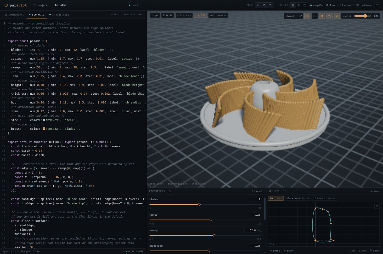
How a browser CAD toy compiles a JavaScript scene into a scene graph, one fragment shader and a uniform pool — and where late-bound edits and each kind of variable enter the pipeline.
Paraplot is a parametric CAD toy that runs in the browser. You describe a solid in JavaScript, drag a few sliders, and a WebGL2 raymarcher draws it. There is no mesh, no kernel and no server: the browser compiles your scene into a fragment shader and renders that.
The whole program is one pipeline:
Every interesting behaviour in the app follows from that chain. Code becomes a data structure; the data structure becomes shader text plus a value pool; the renderer compares the text, links a program when it must, and uploads the pool when it can.
This article walks the chain stage by stage, using one concrete scene: a plate with three holes.
The pipeline, on one diagram
From scene code to a draw call
One concrete scene — a plate with three holes — followed through every artifact. radius and smooth are uniforms; holes is structural. Hover a node, a slot or a routing row; click to pin. The same value lights up in every stage.
chips are uniform slots; the holes loop is structural — it changes the node count, not a slot.
spline edits, at(t) anchors and ruled-surface edges are resolved here. Points enter the render stage through u_points, not the shader text.
program
1 linked program · key = glsl text
draw
fullscreen triangle · raymarch
u_values[14]
u_points · R32F
spline / surface point pool · late-bound
built-ins
camera, resolution, shader clock and material arrays are ordinary uniforms set at draw time.
The two side channels are the whole trick: uniforms change without touching the shader text, while structural variables create nodes and therefore new GLSL. Late-bound geometry is neither — it is resolved into the tree first, then travels in the point pool.
Read it left to right, top to bottom. The code builds a Node tree. The dashed band is the late-binding slot: spline edits, at(t) anchors and ruled-surface edges are resolved there, after build and before generate. generate() turns each node into a GLSL function and appends its numbers to a flat uniform pool. The render stage compares the shader text and uploads the values.
The table at the bottom is the routing map. Hover a row to see where that variable lands in every stage: k.radius is a slot in the pool, k.holes is a node count, spline points go to a texture, and time is a built-in uniform.
1. Code becomes a graph
A scene is a pure function. params declares controls; build(k, t) receives their resolved values and returns a tree of plain records:
export const params = {
  radius: num(0.09, { min: 0.04, max: 0.18 }),
  holes:  int(3, { min: 1, max: 8 }),
  smooth: num(0.05, { min: 0, max: 0.2 }),
};

export default function build(k) {
  const plate = box({ s: [1, 0.12, 1], round: 0.04 });

  const holes = range(k.holes).map((i) =>
    translate([lerp(-1, 1, i / (k.holes - 1)), 0, 0],
      cylinder({ r: k.radius, h: 1 })));

  return smoothSubtract(k.smooth, plate, ...holes);
}
Before build runs, the controls are resolved to ordinary values (resolveParams). k.radius is a number, k.holes is an integer, k.smooth is a number. There are no control objects inside the graph.
The graph itself is a tagged union of records — no classes, no methods, no renderer references:
/* Scene graph. Everything below is plain, serialisable data: the DSL
 * builds it, the compiler consumes it. No behaviour, no references to
 * the outside world. */
export type Node =
  | SphereNode | BoxNode | EllipsoidNode | TorusNode | CylinderNode
  | ConeNode | CapsuleNode | PlaneNode | ImplicitNode
  | SplineNode | ExtrudeNode | LatheNode | OpNode | GroupNode
  | OffsetNode | ShellNode | PaintNode | SurfaceNode | RepeatNode;
Construction freezes the nodes (Object.freeze), so the tree cannot be mutated behind the compiler's back. That purity is what lets the compiler treat a node identity as a cache key: a subtree reused under three transforms is emitted once, and an untouched subtree keeps its identity across an edit.
Two details in this small scene already decide its cost profile:
k.holesis read by JavaScript, inrange(k.holes).map(...). It decides how many cylinder nodes exist. Changing it changes the shape of the graph.k.radiusis read inside each node —cylinder({ r: k.radius }). It becomes a number stored in the node, and later a slot in the uniform pool. Changing it does not change the graph.
k.smooth plays the same role as k.radius, but at the root operation. Hold that thought.
2. Late binding sits between build and generate
A pure build function is not enough, because some edits are not in the source. Dragging a spline control point must not rewrite your JavaScript, and an at(t) anchor must follow the curve while you drag it.
Paraplot adds a second input — overrides — and a fixed resolution order:
build ─→ applySplineOverrides ─→ resolveSplinePointRefs ─→ resolveSurfaces ─→ generateThis is the dashed band in the diagram. It is a linker: the scene can name things before they are defined, and resolution happens later, once the edits are known, in a deterministic order.
- Overrides are per-point offsets, keyed by spline name. Offsets rather than absolute points, so an animated spline keeps moving around the shape you edited.
- References (
rail.at(0.25)) are opaque until this pass. They are resolved against the final tree, so anchors follow the edited curve rather than the source coordinates. - Surfaces are resampled after both, because their edge points are derived from the construction curves.
Each pass is a pure tree transformation with structural sharing: untouched subtrees keep their identity, so a spline reused in several places stays shared and the generated shader text stays stable. Drag a control point below: offsets are applied, both anchors re-resolve, the ruled surface is resampled, and the point pool changes — while the shader text stays fixed.
Late binding: drag the rail
edits are offsets · references resolve afterwardsstructure #e323aeshader text unchangeddrag any control point · dashed = base curve from build() · amber = offsets applied
The bar is a capsule anchored to rail.at(t). References are resolved against the final tree — after offsets — so it follows the curve while you drag. The ruled surface is resampled in the same pass. None of this touches the shader text; only the point pool changes.
This is why spline points do not appear in the shader text. They are resolved into the tree first, then sampled into a point pool that the renderer uploads as a texture (u_points). Late binding is compile-time work, not a runtime lookup.
It is also why the saved document is small. A project stores source, params, overrides and view settings. The graph is never serialised; it is reconstructed by re-running the same pure pipeline.
3. The graph becomes GLSL
generate(root) walks the tree and emits one GLSL function per node. Every function has the same signature — a distance and a material index:
vec2 n2(vec3 p) {
  return vec2(sdCylinder(p - vec3(u_values[4], 0.0, 0.0),
                         u_values[5], u_values[6]), 0.0);
}
For the anatomy scene, the whole program is five node functions plus an entry point:
vec2 n0(vec3 p) {
  vec2 a = n1(p);
  a = opSmoothSubtract(a, n2(p), u_values[13]);
  a = opSmoothSubtract(a, n3(p), u_values[13]);
  a = opSmoothSubtract(a, n4(p), u_values[13]);
  return a;
}

vec2 n1(vec3 p) { return vec2(sdRoundBox(p, v3(0), u_values[3]), 0.0); }

/* n2, n3, n4: the three hole cylinders */

vec2 map(vec3 p) { return n0(p); }
A group does not move its children. It inversely transforms the query point, evaluates the child in local space and scales the distance back:
vec3 q = p;
q -= v3(12);                            // translate
q = rotZ(q, -radians(u_values[15]));    // rotate X then Y then Z
q = rotY(q, -radians(u_values[16]));
q = rotX(q, -radians(u_values[17]));
q /= v3(18);                            // scale (inverse)
vec2 a = child(q);
return vec2(a.x * u_values[21], a.y);   // smallest axis scale
Set operations combine vec2 values and carry the material of the winning child. Bounds are computed on the CPU by a parallel traversal and used to clip the raymarch on the GPU.
The key property is that the shader is a pure function of the graph, not of the parameter values. generate assigns names in traversal order, appends one function per node and concatenates a fixed prelude. Two runs over the same graph produce byte-identical text. That is what makes "did the shader change?" a string comparison later.
It also explains the memoisation. Nodes are deduplicated by identity, and identical paint colours share one material slot. Reusing the same spline object under three transforms is free. Writing the same box(...) three times creates three nodes with three identical functions. The rule rewards building a scene like a program: bind a value, reuse it.
4. Where the variables go
generate produces two things at once: the shader text and a flat Float32Array of numbers. The emitter is tiny:
private f(x: number): string {
  const i = this.values.length;
  this.values.push(x);
  return `u_values[${i}]`;
}
Every primitive calls f (or v3/v2) for its numbers and interpolates the returned index into GLSL. The pool is a single uniform float u_values[N]; accessors assemble vectors from it. Indices are compile-time constants, so the shader never indexes a uniform array dynamically.
Look back at the anatomy table to see the routing:
| Variable | Where it goes | What a change costs |
|---|---|---|
k.radius | u_values[5], [8], [11] | uniform upload |
k.smooth | u_values[13] | uniform upload |
k.holes | 3 cylinder nodes, 3 functions | recompile |
| spline points | u_points texture, via late binding | texture upload |
time | u_time built-in | nothing — the GPU reads it |
Two details are worth spelling out.
The same parameter can occupy several slots. k.radius is captured by each cylinder node, so the pool contains three copies: one per use. The compiler deduplicates nodes and materials by identity, not numbers. k.smooth, by contrast, is emitted once for the root operation and reused in all three combines inside n0. Pool slots are per use site, not per parameter.
Some variables never reach the pool. k.holes was consumed by JavaScript during build. Its effect is structural: three nodes exist because the loop ran three times. There is no u_values slot for it and no amount of uniform upload can change it.
The rest of the pipeline is arranged to push as many variables as possible into the first kind. Three design choices do most of the work.
Keep one code path even when a value is zero. A rounded box with round = 0 is exactly a plain box, but the compiler still emits sdRoundBox:
case 'box':
  // rounded with r = 0 is exactly sdBox; keeping one code path means a
  // rounding parameter can change without recompiling the shader
  return `${sig} { return vec2(sdRoundBox(p, ${this.v3(node.s)}, ${this.f(node.round)}), 0.0); }`;
The special case would save an instruction and cost a recompile the moment the rounding slider leaves zero.
Push the branch into the shader. Smooth operations always take a uniform radius, even at zero, and the GLSL helper branches at runtime:
vec2 opSmoothUnion(vec2 a, vec2 b, float k) {
  if (k <= 0.0) return opUnion(a, b);
  ...
}
So the smoothness slider moves a number, not a decision about which function to call.
Keep expression variables on the same channel. Implicit surfaces use a small expression language compiled to GLSL. The parser accepts an emitVar callback, and the generator passes f, so a named constant becomes a uniform instead of being folded into the text:
const expr = compileExpression(node.source, node.vars, (_name, v) => this.f(v));That is why an implicit gyroid can animate and parameterise without ever rebuilding its shader.
Structural variables are a choice of representation
Some parameters are inherently decisions about the program. The JavaScript loop is the obvious case:
const holes = range(k.holes).map((i) =>
  translate([lerp(-1, 1, i / Math.max(1, k.holes - 1)), 0, 0],
    cylinder({ r: 0.07, h: 1 })));
k.holes = 4 produces four nodes and four functions; 5 produces five. The shader text changes and the program is rebuilt. That is the honest price of describing the shape structurally.
But the same geometry can often be encoded differently. polarRepeat folds the array into one shader function:
const blade = polarRepeat({ count: k.count, spread: k.spread },
  surface({ a: rootEdge, b: tipEdge }));
The shader rotates the query point into the nearest angular sector and evaluates the child once:
float count = max(u_values[countIndex], 1.0);
float sector = 6.283185307179586 / count;
float rad = length(p.xz);
float ang = mod(atan(p.z, p.x) - radians(u_values[offsetIndex]) + 0.5 * sector, sector) - 0.5 * sector;
vec2 best = child(vec3(cos(ang) * rad, p.y, sin(ang) * rad));count, offset and spread are uniforms. A hundred blades cost about the same as eight, and the count never recompiles. The same idea — "repeat a shape around an axis" — has two encodings with opposite cost curves.
Two more representation tricks matter at scale:
- Loop bounds are uniforms, not literals. In
surface, the ruling count and GLSL step count are pushed into the pool. A literal bound makes the driver unroll the loop, which can take more than ten seconds to compile on ANGLE; a dynamic bound keeps it rolled. - Large point arrays go into a texture. Splines and surface edges are hundreds of
vec3s. The same flat buffer is uploaded as anR32Ftexture, and the shader reads point data withtexelFetch. Scalars come fromu_values; geometry comes fromu_points.
Compiler inspector
same shape, two encodingsshader #2b62f1936 fns17 uniforms1 compileNumeric parameters become slots in a flat u_values pool. Only a change in the graph's shape changes the shader text and forces a recompile.
const plate = box({ s: [1, 0.12, 1], round: 0.04 });const holes = range(k.holes).map((i) =>translate([lerp(-1, 1, i / (k.holes - 1)), 0, 0],cylinder({ r: k.radius, h: 1 })),); // ^ structuralreturn subtract(plate, ...holes);
green chips are uniform slots; hover one (or a shader line) to link them
uniform float u_values[17];vec3 v3(int i) { return vec3(u_values[i], u_values[i + 1], u_values[i + 2]); }float sdRoundBox(vec3 p, vec3 b, float r) {vec3 q = abs(p) - (b - r);return length(max(q, 0.0)) + min(max(q.x, max(q.y, q.z)), 0.0) - r;}float sdCylinder(vec3 p, float r, float h) {vec2 d = vec2(length(p.xz) - r, abs(p.y) - h);return min(max(d.x, d.y), 0.0) + length(max(d, 0.0));}vec2 opSmoothSubtract(vec2 a, vec2 b, float k) {if (k <= 0.0) return vec2(max(a.x, -b.x), a.y);float h = clamp(0.5 - 0.5 * (-b.x - a.x) / k, 0.0, 1.0);return vec2(mix(-b.x, a.x, h) + k * h * (1.0 - h), a.y);}vec2 n1(vec3 p) { return vec2(sdRoundBox(p, v3(0), u_values[3]), 0.0); }vec2 n2(vec3 p) {vec3 q = p - vec3(u_values[4], 0.0, 0.0);return vec2(sdCylinder(q, u_values[5], u_values[6]), 0.0);}vec2 n3(vec3 p) {vec3 q = p - vec3(u_values[7], 0.0, 0.0);return vec2(sdCylinder(q, u_values[8], u_values[9]), 0.0);}vec2 n4(vec3 p) {vec3 q = p - vec3(u_values[10], 0.0, 0.0);return vec2(sdCylinder(q, u_values[11], u_values[12]), 0.0);}vec2 n5(vec3 p) {vec3 q = p - vec3(u_values[13], 0.0, 0.0);return vec2(sdCylinder(q, u_values[14], u_values[15]), 0.0);}vec2 n0(vec3 p) {vec2 a = n1(p);a = opSmoothSubtract(a, n2(p), u_values[16]);a = opSmoothSubtract(a, n3(p), u_values[16]);a = opSmoothSubtract(a, n4(p), u_values[16]);a = opSmoothSubtract(a, n5(p), u_values[16]);return a;}vec2 map(vec3 p) { return n0(p); }
Move a slider: green slots update silently, an amber slot changes the graph and recompiles.
The inspector above is the same split, live. Drag radius (a uniform) and the shader hash stays fixed; change the hole count with the JS-loop encoding and the hash changes. Toggle to polarRepeat and the same count becomes a uniform. Hover a slot or a shader line to see the correspondence.
Where a change stops
Every edit enters the same pure pipeline. The fork after generate() decides whether the GPU program is reused or rebuilt.
The graph is rebuilt and re-emitted, but the shader text is byte-identical. The renderer keeps the linked program and uploads the new value pool.
numeric parameter · full pipeline
The map above is the same idea across edit kinds: every change runs the pure pipeline, but only some changes produce new shader text. Numeric, spline and graph-animation edits stop at the uniform upload; a structural edit pays for a program link. A shader-clock animation bypasses the CPU pipeline entirely.
Two clocks
build(k, t) can take a time argument. The compiler detects the second parameter and the worker re-runs the pipeline every frame. Since time is just another input, the graph is rebuilt and the pool is refreshed; as long as the structure does not depend on t, the shader text is unchanged.
The second clock is cheaper. An implicit equation can read time directly, which the parser maps to the built-in u_time:
implicit('abs(sin(x*f + time*s) * cos(y*f)) - th', {
  vars: { f: 6, th: 0.4, s: 0.5 },
  bounds: 1.6,
});
The generator sees u_time in the emitted expression, sets usesTime, and the renderer advances the clock itself. No worker round-trip, no JavaScript per frame. The rule that keeps the first clock cheap is that structure must not depend on time: adding or removing nodes as t advances would change the shader every frame.
5. Render: reuse the program, upload the numbers
The renderer receives a program and compares its shader text to the last one:
if (scene.glsl !== this.glslKey) {
  ...compile and link...
  this.glslKey = scene.glsl;
}
this.values = scene.values;
this.materials = scene.materials;
this.bounds = scene.bounds;
Same text means the linked program is reused; only the value pool changes. A failed shader is remembered as failed, so a broken edit does not retry on every frame. Programs are cached by (view mode, shader source), and analysis views (normals, curvature, zebra, gradient) reuse the base program until their variant is linked.
The worker omits unchanged payloads on the wire: the GLSL is dropped when it is byte-identical, as are the tree, schema and spline lists. The value buffer is transferred, not copied. On the GPU, one fullscreen triangle runs one fragment shader that raymarches the scene, evaluates materials and writes the frame.
Rendering is demand-driven. A dirty flag and a live predicate decide whether to run a frame; a static scene stops the requestAnimationFrame loop and sits at idle. While orbiting, the buffer drops to a draft resolution, shadows are skipped and the march budget is reduced; a refinement frame follows. The first frames are a low-quality probe, and a measured ramp picks a sustainable scale. A worker owns the GL context on an OffscreenCanvas (with a main-thread fallback), so shader compilation and draw submission do not block the UI thread.
Driving the pipeline
The UI does not hold a scene graph in state. It holds inputs and derives the program. Compiles run in a worker; the client keeps only the newest queued request and applies results with startTransition. Text edits are debounced (110 ms), slider values are throttled (45 ms, leading and trailing), and a compile is issued at the current animation time so a live scene does not snap back to its start pose.
A compile result is data, not an exception. { ok: false, error } goes to the error banner while the last good program keeps rendering, and a worker that takes more than ten seconds is terminated and respawned lazily. The timeline below runs one drag through the machinery: pointer samples, throttle, worker, coalesced requests, and the single structural edit that changes the shader text.
One drag, through the scheduler
16 ms pointers → 45 ms throttle → workerThe worker never builds a backlog. A slower compile simply causes more requests to be replaced by newer ones.
The drag is about to start. Every pointer sample re-renders the panel; the throttle decides which ones become compile requests.
57 pointer samples · 20 drag requests + 1 structural · 9 compiles · 12 coalesced · 1 link
What the pipeline buys
The architecture is the performance model:
- Numeric edits never recompile. They rewrite pool slots.
- Structural edits recompile once. They change the node tree, and therefore the functions.
- Late-bound edits change neither. They resolve into the tree and the point pool, leaving the shader text alone.
- Shaders are cacheable artifacts. Byte-identical text can be compared, cached by source and view mode, and shown verbatim in the editor's shader tab.
- Projects are plain records.
source + params + overridesreconstructs the document. - Shared subtrees are free. Reusing a node object emits one function and one set of slots.
- Errors are values. The last good program stays on screen while the editor explains what broke.
It also has costs. Structural parameters are expensive by construction. Bounds are conservative, so intersections can over- or under-estimate. Non-uniform scale uses the smallest axis scale for distances. Smooth blends with a large k can violate the distance bound. Implicit fields are normalised by a finite-difference gradient, which costs six extra field evaluations per march step. Large point arrays need a texture path. And no amount of purity saves a scene that is simply expensive to compile; the timeout and worker respawn bound the damage.
None of these are accidents. They are the price of a pipeline where geometry is a value: cheap to copy, cheap to compare, cheap to re-derive when it must change.
If you want to try it, the app is at nikhedonia.net/paraplot and the source is on GitHub. Open the shader tab next to the editor to see the compiled artifact for the scene you are building; it is the same text the renderer receives.
Related Articles
Hamilton: A Phase-Space Playground
Type a Hamiltonian or Lagrangian, integrate it in the browser, and watch an entire phase space evolve. A WebGL2 playground with RK4, symbolic derivatives and 21 built-in systems.
Conformal Clifford Algebra: Points, Rotors and a Robot Arm
Embed 3D geometry in a 5D Clifford algebra where points, circles, spheres, planes and lines are all blades. A playground for N-joint inverse kinematics, curve and surface intersections.
The Challenges of WebGL
WebGL lets you run shaders in the browser — and that's genuinely magical. But using it for arbitrary GPU computation quickly reveals a thicket of constraints that OpenCL and WebGPU were designed to escape.